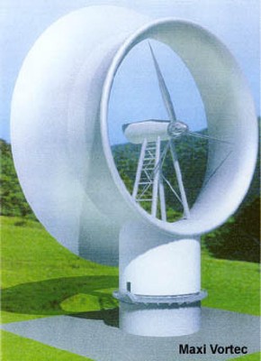
In 1972 Dr. James T. Yen invented the concept of the Tornado Wind Energy
Conversion System (TWECS). The TWECS captures the windstream and guides it into
a cylindrical tower which entrains it into a tornado-like vortex. The vortex
creates a column of very low pressure within its core; the bottom of which
interacts with the floor of the tower. This is where a horizontal
(vertical-axis) turbine is placed. The low pressure above (behind) the turbine
acts as a powerful exhaust reservoir to draw air through the turbine. As long as
the wind into the tower is sufficient, the vortex is self-sustaining. The TWECS
tower concentrates the windstream in much the same way as a convex lens
concentrates sunlight, enabling it to do more work.
Testing by Yen and others has shown that the Coefficient of Power (Cp) of a TWECS is anywhere from 5 to 22 times that of the conventional wind turbines in use today (see references). And since it will not cost 5 to 22 times the amount to build, the TWECS promises to dramatically reduce the cost of wind-generated power.
In order to fully understand the significance of the TWECS, it is necessary to understand a few basics of wind power.
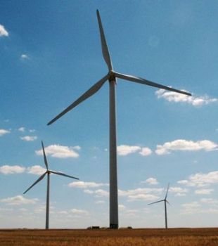
Conventional Wind Energy Conversion Systems (WECS), also known as Horizontal-Axis Wind Turbines (HAWTs), extract kinetic energy from the wind by simultaneously accelerating the turbine blades and decelerating the wind. The formula, called Coefficient of Power (Cp), calculates the efficiency of a wind energy system.
Cp = Energy produced by wind energy system
Total kinetic energy in wind
According to Belz Law (also called the Betz Limit), HAWTs are limited to a maximum theoretical Cp of 0.593 (59.3%). The reason a HAWT can’t extract 100% of the power from the wind is because the turbine blades slow down the windstream in front of the turbine causing the air molecules to get bunched up. This “traffic jam” prevents the windstream from flowing smoothly through the turbine and reduces efficiency.
Kinetic energy increases by the square of the wind speed; which is why you want to place your wind turbine in a windy location.
It had been known for some time, however, that enclosing the turbine’s rotor blades in a shroud or duct significantly increases efficiency.
Technically, this duct is called a convergent-divergent diffuser and the whole system is usually called a Diffuser-Augmented Wind Turbine (DAWT) or simply a Ducted Wind Turbine (DWT). The diffuser is actually an airfoil that surrounds the turbine just clear of the blades tips, is narrower in front and expands in diameter downwind. This configuration creates a drop in air pressure behind (downwind of) the rotor blades allowing increased airflow through the turbine causing a 5 to 6-fold increase in power (Anderson 1997), with a calculated Cp of ~2.0 (200%) (Phillips et al, 1998).
Remember the traffic jam of wind molecules bunched up in front of the HAWT turbine blades? The drop in air pressure caused by the DAWT’s diffuser behind the rotor blades functions like a giant vacuum cleaner nozzle and “pulls” more air through the turbine.
At first glace it may appear that the DAWT is violating Betz Law; extracting more energy from the wind than exists in the wind (in the above example 200%). The reason this appears to be so is because the Cp formula can only calculate the percentage of kinetic energy extracted from the wind. The DAWT captures the kinetic energy of the wind as well as capturing a certain percentage of the flow-pressure energy of the wind.
Kinetic Energy vs. Flow-Pressure Energy
Kinetic energy is defined as the energy a substance or body possesses by virtue of its motion relative to a reference plane (Prakashan 2009). To calculate kinetic energy you multiply half the weight (mass) of the substance or body by its velocity squared (½M x Vel2)
Flow-pressure energy is defined as the energy a substance possesses by virtue of the space it occupies. It is most often associated with flowing streams of incompressible liquids under pressure (Prakashan 2009). To calculate flow-pressure energy you first multiply pressure times volume, then multiply that product by its velocity cubed (P x Vol) x V3).
(Introduction to process calculations (stoichiometry), Nirali Prakashan, Jan.
2009 isbn 978-81-906316-6-8)
Some examples will help clarify the difference:
You have a straw in a glass of water. The water in the straw is at the same level as in the glass. You put your mouth to the straw and suck. This sucking action lowers the pressure in the straw between the water and your mouth so the water rises up the straw and into your mouth. The energy you used to move the water is flow-pressure energy, not kinetic energy. When you remove your mouth from the straw, kinetic energy (powered by gravity and atmospheric pressure) pushes the water down the straw and back into the glass.
Another example is sailing. If kinetic energy were the only kind of energy in the wind, a sailboat would only be able to sail in the direction of the wind or at an angle away from the wind. But as all sailors know – with the proper sails, trimmed appropriately – a sailboat can tack into the wind. It can do this because tacking into the wind causes reduced pressure on the forward part of the sail which “sucks” the sailboat forward at an angle against the wind. In fact, there is so much pressure energy in the wind that the sailboat can tack into the wind faster than the wind speed! This is proof that there is more flow- pressure energy in the wind than there is kinetic energy. (http://terrytao.wordpress.com/2009/03/23/sailing-into-the-wind-or-faster-than-the-wind/)
An oversimplified explanation would be: kinetic energy pushes and flow pressure energy sucks.
Flow-Pressure Energy REALLY Sucks!
There is, in fact, far more flow pressure energy in the wind than there is kinetic energy. Yen estimated that there is 3600 times more flow pressure energy in the wind than kinetic energy (Jan 24, 1978; US Patent No. 4,070,131).
And remember when we said that kinetic energy increases by the square of the wind speed? Well, flow-pressure energy increases by the cube of the wind speed!
So, it would seem that it’s far more fruitful to design a wind turbine to extract more flow pressure energy from the wind, than to extract more kinetic energy.
Tornados Really Suck
Dr. Yen realized that the pressure drop inside the vortex of strong atmospheric tornados is as much as 100 millibars; far greater than the pressure drop behind a DAWT. So he designed a wind turbine that generates a tornado-like vortex to create a much greater pressure drop across the turbine.
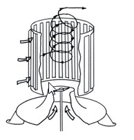
He did this by using a cylindrical tower with vertical louvers that could be opened and closed in response to wind direction. The louvers on the upwind side of the tower would be opened to admit the windstream, while the downwind louvers would be closed. The windstream would then be entrained into a tornado-like vortex. A vertical-axis turbine is put at the bottom of the tower. The low pressure of the vortex core “sucks” ambient air thru the bell shaped cone, through the turbine, into the vortex and is exhausted out the top of the tower. As long as the wind speed is sufficient the vortex is self-staining.
It’s obviously a great idea. But there is a fly in this ointment. As envisioned by Yen, the vertical louvers are opened and closed with motors. These motors have to coordinate the louver’s opening and closing in response to wind direction, even with rapidly changing wind directions, and do this in real time – to successfully entrain a robust vortex. A tall order! To my knowledge, no one ever even attempted to build a working model of Yen’s original design.
But that didn’t stop the research. Various models were tested.
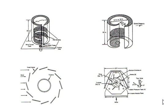
The models tested fell into 2 general categories: uni-directional and omni-directional. The two top models above are uni-directional (one circular and one spiral). The two bottom models are omni-directional (one fixed vane and one flexible vane).
The uni-directional models worked well. They were able to entrain robust tornado-like vortices and produced Cps from 2.5 all the way up to 9 (that’s 5 to 22 times the efficiency of a HAWT!)
The omni-directional models didn’t fare as well. None of the omni-directional models tested could create and sustain a robust tornado. That’s really too bad because the uni-directional models are of limited usefulness because it’s impractical to build a turntable that can keep a large uni-directional TWECS pointed into the wind.
This is where The New Approach comes in: The New Approach TWECS Tower
Sorry: Drawing removed until patent has been applied for.
The outer vanes are fixed. They catch the windstream and direct it into the tower’s core. The inner vanes are hinged and swing freely toward the center of the tower. The windstream on the upwind side pushes them open and the wind going around the downwind side sucks them closed. The windstream is thus entrained into a vortex. And since the inner vanes are wind driven, they automatically adjust to changes in wind direction. This configuration creates a TWECS that is as omni-directional as any other vertical-axis wind turbine.
Bench tests conducted by Dr. Jean-Jacques Chattot show that The New Approach TWECS design does indeed entrain the wind into a vortex that appears to be just as robust as those created by other researches with uni-directional models. These were preliminary tests so no data were collected.
If The New Approach to the TWECS tests out as expected, it will produce a Levelized Electricity Cost (LEC) of half that of burning coal; and thus, usher in a new era in wind-energy technology.
We have also integrated several other innovative concepts into The New Approach tower.
As Above, So Below
There are three ways to create a pressure differential across a TWECS turbine: by lowering the pressure above the turbine (as we have just described), by increasing the pressure below the turbine, or by doing both at the same time. Pressure can be increased below the turbine by making use of an upwardly curved conical structure that directs the windstream in an upward fashion into the bottom of the turbine.
Turbine Design
Because of the increased air-flow through the turbine, the RPM will be much higher than a HAWT’s. In a model wind-tunnel tested by Yen (1982) a 10-bladed turbine rotor achieved rpms in excess of 5600. Because of this, we will use a multi-bladed turbine rotor that resembles a bicycle-wheel with airfoils as the spokes.
Magnetic Levitation
In this design, the turbine is situated between two bell-mouths that form an hourglass shape. This configuration gives us a unique opportunity to dispense with the turbine’s central shaft by suspending the turbine along its outer rim with magnetic levitation.
The best form of magneto-dynamic (repulsive) levitation for our purpose is the Inductrack System invented by Dr. Richard Post of the Lawrence Livermore National Laboratory (LLNL) USA (U. S. Patent No. 5722326, March 3, 1998). Since the Inductrack System does not rely on eddy currents induced in conducting surfaces, the ratio of lifting force to drag force is much higher than other MagLev systems (200:1 at high speed). In fact, at high speed the lifting force is 50 times the weight of the magnet (Post 1998). The lift-to-drag ratio is so high, only a small percentage (1% or so) of the wind energy needs to be used for levitation. And, since the Inductrack System is truly passive and requires no electronic control system, it is ideal for our purpose.
Levitation and Power Generation in One Package
Using the Inductrack System has an additional advantage. The flux lines of the array are aligned in two directions: parallel to the direction of motion (in our case, horizontal) and perpendicular to the direction of motion (in our case, vertical). The horizontal flux lines are responsible for inducing the levitation force. The vertical lines of flux can, therefore, be used to generate electricity in the same coil that produces the lifting force (without interfering with the levitation) by adding turns of wire threading the high-permeability core. These stator coils could be wired to produce either DC current or 3-phase, 60-hertz output. The arrangement simultaneously produces both a magnetic bearing and an efficient, direct-drive, linear induction generator.
Electro-Mechanical Batteries for Power Conversion
Electro-mechanical batteries (EMBs, aka: flywheels) can perform the functions of energy storage and power conversion simultaneously. The freewheeling, fixed-pitched blade turbine can be electrically or magnetically coupled with one or more EMBs. Since EMBs can be charged with variable frequency / voltage input, they can capture and store the energy and then convert the stored energy into 3-phase, 60 Hz, 130 volt, utility grid-quality electricity upon demand (Post 1999).
This arrangement has 2 major advantages: 1) it eliminates the energy-robbing gearbox, and 2) the fast moving rim provides more angular momentum, and thus more energy, than a conventional central shaft-driven generator. This system will not only achieve greater conversion efficiency over conventional power electronics, but has obvious advantages in an era of smart grids and distributive generation.
Electro-Mechanical Batteries for Electro-Magnetic Braking
The power curve of conventional HAWTs drops off dramatically in high winds because the rotor blades are not engineered for high RPMs and must be braked. This wastes energy. The New Approach TWECS uses electro-magnetic braking. Dangerously high RPMs are prevented by bringing more EMBs on-line. The additional EMBs produce more electro-magnetic resistance which simultaneously controls RPMs and generates (and stores) more energy.
Electro-Mechanical Batteries for Energy Storage
If the TWECS produces more energy than can be immediately used, the excess energy can be stored in EMBs and later released when the system is generating less power.
Am I Getting A Bit Too Technical For You? Think About It This Way:
The rim of the bicycle-wheel turbine is like a MagLev train on a circular track. When pushed by the wind, it generates electricity in much the same way as the Toyota Prius does when using regenerative braking. The harder the braking, the more energy is produced. This technology is 20-30 years old; is just hasn’t been applied to wind turbines!
Coefficient of Power
Since the proposed tower design has not been wind-tunnel tested it is impossible to quote Cp. Hsu & Ide (1982), however, produced a Cp of 9 with a uni-directional spiral model based on this curve:
When you superimpose this spiral on the geometry of The New Approach TWECS you can see that the curves are very similar.
Sorry: Drawing removed until patent has been applied for.
Hsu & Ide incorporated a stagnation chamber below the turbine, while The New Approach incorporates a ram-air configuration. Given these similarities with the best TWECS tower ever tested, we believe it is reasonable to expect a similar Cp.
Advantages of The New Approach
The New Approach to the Tornado Wind Energy Conversion System embodies a number of advantages over conventional HAWTs. The TWECS tower configuration…
-
is omni-directional
-
the tower captures wind from a much larger cross-section of the wind stream than the rotor-sweep of a HAWT
-
uses a stationary wind-gathering structure
-
creates a low-pressure exhaust reservoir behind the turbine blades
-
uses a much smaller turbine per unit of energy produced
-
creates much higher turbine RPMs
-
uses a vertical-axis turbine
-
puts the generator closer to the ground for easier maintenance
-
will reduce bird kills to nearly zero
-
places the generator completely out of the wind stream
-
uses magnetic levitation to reduce friction
-
does not require turbine blades to pitch
-
requires no yaw mechanism
-
can store energy in one or more flywheels
-
can extract usable energy from both low speed and high speed winds more efficiently
-
increases distributive generation by allowing the wider distribution of machines
-
uses permanent magnet excitation
-
is silent in operation
-
adjusts instantly to changes in wind direction without loss of efficiency
Dr. Yen’s idea of using a tornado-like vortex to create a low-pressure exhaust reservoir for a vertical-axis turbine has great potential. This potential was left unfulfilled in the 70’s and 80’s because a practical, cost-effective tower that adequately created, contained and concentrated a vortex could not be produced. The tower design of our New Approach fulfills this potential. Adequate funding is required to test the proposed tower design and to investigate the use of magnetic levitation and electromechanical batteries to further increase the system’s efficiency.
References
Blair, C., Jacobs, N., Quiram, J., (1999). Electrical Power and Supply. In B. Cornelia, N. Jacobs and J. Quiram (Eds.), Energy -- Shortage, Glut or Enough (pp. 122--141). Wylie, TX: Information Plus.
Hsu, C. T., and Ide, H., (1982). Effect of Radial Inflow on Vortex Intensification for a Tornado-Type Wind Turbine (ISU-ERI-Ames 83073). Sept. 1982. Iowa State University, Ames, Iowa.
Hsu, C. T., (1983). Tornado Type Wind Turbines. United States Patent No. 4452562. May 6.
Jacobs, E. W. (1983). Research Results for the Tornado Wind Energy System: Analysis and Conclusions. Proceedings of the ASME Solar Energy Division Fifth Annual Conference, April 18-21, pp. 606-617.
Miller, G., Hoffert, M., Corren, D., Hseih, W., and Volk, T. (1981). The Tornado Wind Energy Conversion (TWECS) Evaluation Program at New York University (NYU/DAS 81-15). July 1981. New York University, New York, NY. New York State Energy Research and Development Authority, Albany, NY.
Phillips, D. G., Flay, R. G. J., Nash, T. A., (1998). Aerodynamic Analysis and Monitoring of the Vortec Seven Diffuser Augmented Wind Turbine. Proceedings of the Annual Conference of the Institute of Professional Engineers NZ, Auckland.
Post, Richard F., (1999). Personal communication via e-mail dated July 6.
Yen, J. T., (1979). Tornado-Type Wind Energy System (RE-571). March 1979 (Revised April 1980). Grumman Aerospace Corp., Research and Development Center, Bethpage, NY.
Yen, J. T. (1982). Investigations of the Tornado Wind Energy Systems (SERI/TR-110521). June 1982. Grumman Aerospace Corp., Research and Development Center, Bethpage, NY.